SLWF-09
- Introduction
- Hardware Overview
- Wiring and Installation
- Firmware Setup
- GPIO Allocation
- Troubleshooting
- Technical Specifications
- Frequently Asked Questions (FAQ)
- Note about device disassembling
Introduction
Thank you for choosing the SMLIGHT SLWF-09, our most flexible, modular, and feature-rich LED controller to date.
Designed for enthusiasts, makers, and professionals, the SLWF-09 combines ESP32 processing power with the user-friendly WLED firmware to deliver stunning lighting effects for addressable LED strips.
Whether you need a simple Wi-Fi setup or a professional wired installation with PoE, the SLWF-09 adapts to your needs with plug-and-play add-on modules.
Key Features
-
ESP32-based with 16 MB flash – powerful, reliable, and customizable.
-
Pre-flashed with WLED – start controlling your LEDs immediately.
-
Modular add-on support:
-
Ethernet Module – stable wired network connectivity.
-
⚡ PoE Module – single-cable power and data.
-
Microphone Module – unlock sound-reactive effects in WLED.
-
-
Compatible with popular LED types: WS2812B, SK6812, APA102, and more (5V–12V).
-
Supports two LED channels by default, expandable up to six via GPIO.
-
Integrates seamlessly with Home Assistant, Node-RED, and other smart home platforms.
What’s in the Box
-
SLWF-09 main controller board
-
Quick-start guide
-
(Optional) Ethernet, PoE, or Microphone add-on modules if purchased together
About This Manual
This manual will guide you through:
-
Hardware overview – understanding your SLWF-09 and add-ons
-
Wiring and installation – safe connection of LEDs and power
-
Firmware setup – configuring WLED and integrations
-
GPIO allocation – reference table for advanced users
-
Troubleshooting – solutions to common issues
Important Notes
-
Always disconnect power before attaching or removing add-on modules.
-
Use a compatible power source matching your LED voltage (5V, 12V).
-
If using the PoE module, ensure your network switch or injector supports IEEE 802.3af and you use 5V LED strip
Hardware Overview
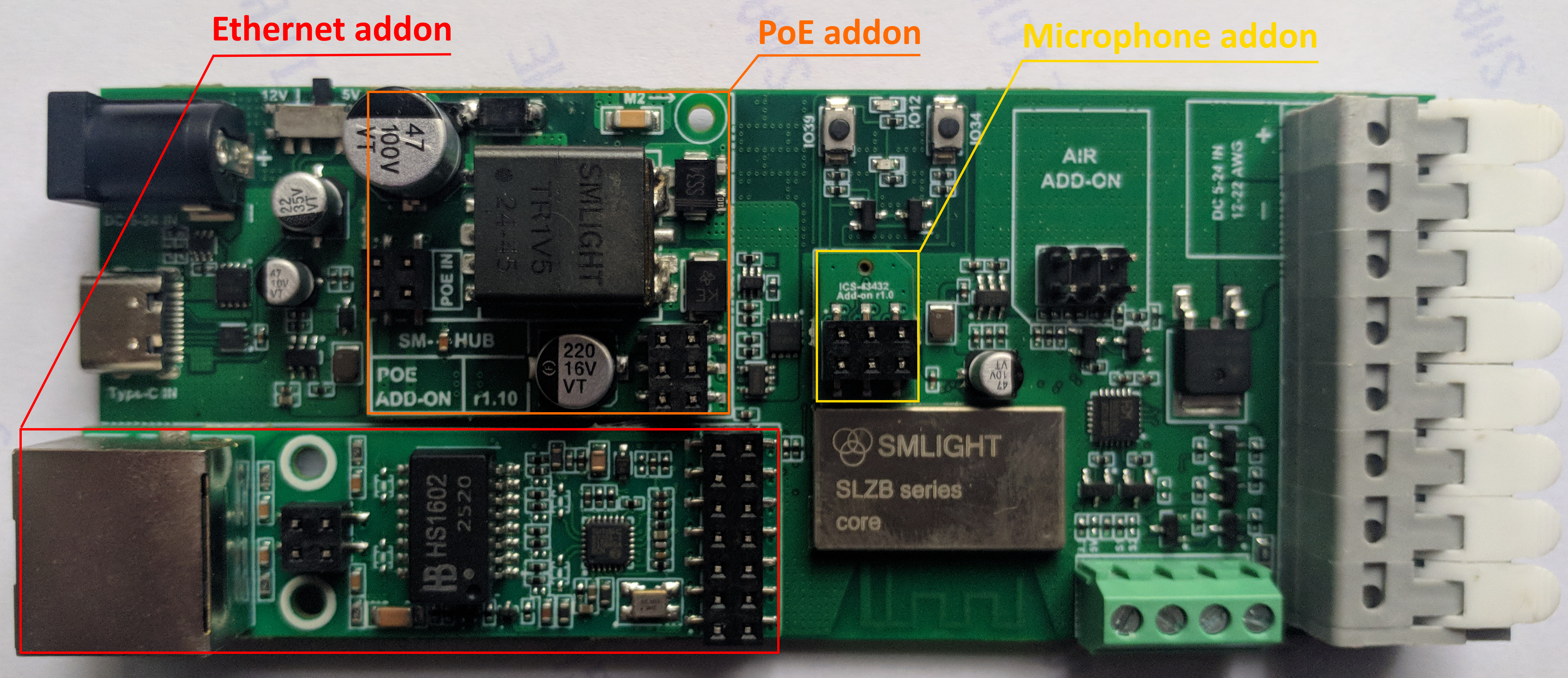
The SMLIGHT SLWF-09 is designed as a modular, ESP32-based LED controller with optional add-on boards for Ethernet, Power over Ethernet (PoE), and digital microphone functionality. This section describes the main components and interfaces of the SLWF-09 and its supported add-ons.
2.1 Main Board Features
-
ESP32-D0WD-V3 microcontroller with 16 MB flash memory
-
Pre-installed WLED firmware for plug-and-play operation
-
Two LED control channels by default (expandable to six via GPIO)
-
USB-C port with UART auto-flash for firmware updates
-
Power input options:
-
USB-C (supports PD negotiation - can drive either 5V ortr 12V LED strips)
-
VIN screw terminal (5–12V)
- DC plug in (5-12V)
- Wire terminal (5-12V)
-
PoE module (optional, 5V 800mA output)
-
-
Two on-board buttons for mode selection and reset
-
Expansion headers for add-on modules (Ethernet, PoE, Microphone, future expansions)
-
Level-shifted LED outputs for wide LED voltage compatibility (level shifting 5V)
- DIY Terminal - for external buttons sensors or relays.
2.2 Add-on Modules
2.2.1 Ethernet Module (Optional)
-
Based on LAN8720 Ethernet PHY
-
Standard RJ45 connector with integrated magnetics and status LEDs
-
10/100 Mbps full-duplex operation
-
Connects directly to the SLWF-09 via dedicated header
-
Can be used standalone or with the PoE module
Benefits:
-
Reliable, low-latency connection for installations where Wi-Fi is unstable or not preferred
-
Full Home Assistant and WLED Ethernet support
2.2.2 PoE Module (Optional)
-
IEEE 802.3af compliant (PoE Class 0)
-
Integrated DC/DC converter provides regulated 5V (up to 800mA) power to the SLWF-09
-
Connects between Ethernet add-on and network cable
-
Eliminates the need for a separate power adapter
Benefits:
-
Single-cable solution for both data and power
-
Ideal for ceiling, wall, or inaccessible installations
2.2.3 Microphone Module (Optional)
-
ICS-43432 digital MEMS microphone
-
Connects via dedicated header to ESP32 I²S pins
-
Used by WLED to enable sound-reactive LED effects
-
No additional power supply required (powered from main board)
Benefits:
-
Real-time music synchronization without external sound sensors
-
High-quality digital audio sampling
2.3 Physical Dimensions
-
Main Board: approx. 57 × 30 × 23 mm
-
Ethernet Module: approx. 60 × 18 × 15 mm
-
PoE Module: approx. 31.5 × 28.7 × 16 mm
-
Microphone Module: approx. 15 × 12 mm
2.4 Connectivity Summary
| Interface | Description |
|---|---|
| USB-C |
Power input (5V or 12V - based on switch selector) and UART programming |
| VIN | Screw terminal power input (5–12V) |
| LED OUT 1/2 | Two independent addressable LED channels |
| Add-on Ports | Headers for Ethernet, PoE, and Microphone modules |
| Buttons | Boot/flash and reset/mode selection |
Wiring and Installation
This section explains how to connect the SLWF-09 controller, add-on modules, and LED strips safely and correctly.
Follow all instructions carefully to ensure reliable operation and to avoid damage to the controller or connected equipment.
3.1 Safety Precautions
-
Disconnect power before attaching or removing any cables or add-on modules.
-
Verify that your LED strip voltage matches the power supply voltage (5V, 12V).
-
Never connect different voltage levels (e.g., 12 V LED strip with 5 V power supply).
-
When using PoE, ensure your network switch or injector supports IEEE 802.3af. Please limit the current for the LED strip to 800mA
-
Observe correct polarity when wiring power and LED connections.
3.2 Powering the SLWF-09
You can power the SLWF-09 in three different ways:
-
USB-C port – 5V or 12V
-
Ideal for testing, firmware updates, or low-power LED setups.
-
Supports USB PD for negotiation, can supply 5V or 12V.
-
-
DC plug-in – 5V to 12V DC
-
Connect a DC plug into DC plug-in connector.
-
DC "+" goes to LED strips through the onboard MOSFET (relay) switch or to VCC directly bypassing MOSFET (relay).
-
-
Wire fast-connect terminal – 5V to 12V DC
-
Connect a wire directly to the VIN (+) and GND (–) terminals.
-
VIN also powers the LED strips through the onboard MOSFET switch.
-
-
PoE Module (optional) – IEEE 802.3af
-
Provides 5V 800mA from an Ethernet connection via a PoE-enabled switch or injector.
-
Can be used together with the Ethernet add-on for single-cable operation.
-
3.3 Connecting LED Strips
The SLWF-09 supports most addressable LED protocols, including WS2812B, SK6812, APA102, and others.
Steps:
-
Identify your LED strip’s Data (and optional Clock) lines, V+, and GND.
-
Connect LED OUT 1 or LED OUT 2 on the SLWF-09 to the corresponding LED strip input:
-
Data → DATA pin
-
Clock → CLOCK pin (only for clocked LED types such as APA102)
-
V+ → LED supply voltage (must match power source)
-
GND → Common ground between SLWF-09 and LED strip
-
-
If controlling long LED runs, use an external power injection every several tens of meters to avoid voltage drop.
3.4 Installing Add-on Modules
3.4.1 Ethernet Module
-
Align the module with the Ethernet header on the main board.
-
Insert firmly, ensuring the keyed connector matches the socket.
-
Connect your network cable to the RJ45 port.
3.4.2 PoE Module
-
Install the PoE module between the Ethernet add-on and network cable.
-
Connect the network cable from a PoE switch/injector to the module.
-
The module will automatically power the SLWF-09.
3.4.3 Microphone Module
-
Align the module with the MIC header on the main board.
-
Insert carefully; the keyed connector ensures correct orientation.
-
Enable sound-reactive mode in WLED settings.
3.5 First Power-On
-
Double-check all wiring connections.
-
Apply power via your chosen method.
-
Observe the status LEDs:
-
Power LED – solid on when powered
-
Status LED – WLED activity indicator
-
-
Connect to the SLWF-09 via Wi-Fi or Ethernet to complete setup.
3.6 Recommended Installation Tips
-
Mount the SLWF-09 in a ventilated place to protect from dust and accidental contact.
-
For permanent installations, secure cables with strain relief.
-
Keep data wires short to reduce signal degradation.
-
Use twisted pair or shielded cable for long data runs.
Firmware Setup
-
The SLWF-09 comes pre-flashed with the latest stable WLED firmware, allowing you to start controlling LEDs right out of the box. This chapter explains how to connect to WLED for the first time, configure network settings, and update or change the firmware when needed.
4.1 First Connection to WLED
-
Power on the SLWF-09 using your chosen method (USB-C, VIN, or PoE).
-
The device will create a Wi-Fi Access Point (AP) named:
WLED-APDefault password:
wled1234 -
Connect your phone or computer to this Wi-Fi network.
-
Open a web browser and go to:
http://4.3.2.1 -
In the Wi-Fi Setup section, enter your home network SSID and password.
-
Save and allow the SLWF-09 to reboot.
After reboot, it will connect to your home network and get an IP address from your router.
4.2 Ethernet Connection (Optional)
If you have installed the Ethernet add-on:
-
Connect the Ethernet cable to your router/switch.
-
The SLWF-09 will automatically obtain an IP address via DHCP.
-
You can access WLED using this IP address directly.
4.3 Updating the Firmware
The SLWF-09 supports OTA (Over-The-Air) updates as well as flashing via USB-C.
Method 1 – OTA Update
-
Open the WLED web interface.
-
Go to Config → Security & Updates.
-
Select Manual OTA Update.
-
Upload the new
.binfirmware file.
Method 2 – Web-based Flasher
You can easily flash the SLWF-09 directly from your browser using our official online flasher:
-
Requires Google Chrome or Microsoft Edge.
-
Connect the SLWF-09 to your computer via USB-C.
-
Follow the on-screen instructions to install WLED, ESPHome, or other compatible firmware.
Method 3 – USB-C via esptool
-
Use
esptool.pyor similar utilities for advanced flashing. -
Hold BOOT (GPIO0) during power-up to enter programming mode.
4.4 Switching Firmware (WLED ↔ ESPHome)
-
You can replace WLED with ESPHome for integration with Home Assistant.
-
When switching from WLED to ESPHome, use the Web-based Flasher or esptool method.
4.5 Restoring Factory Defaults
-
To reset network settings:
-
Hold the Boot/Flash button for 5+ seconds while powered.
-
Release when the status LED blinks rapidly.
-
-
The device will reboot into AP mode.
-
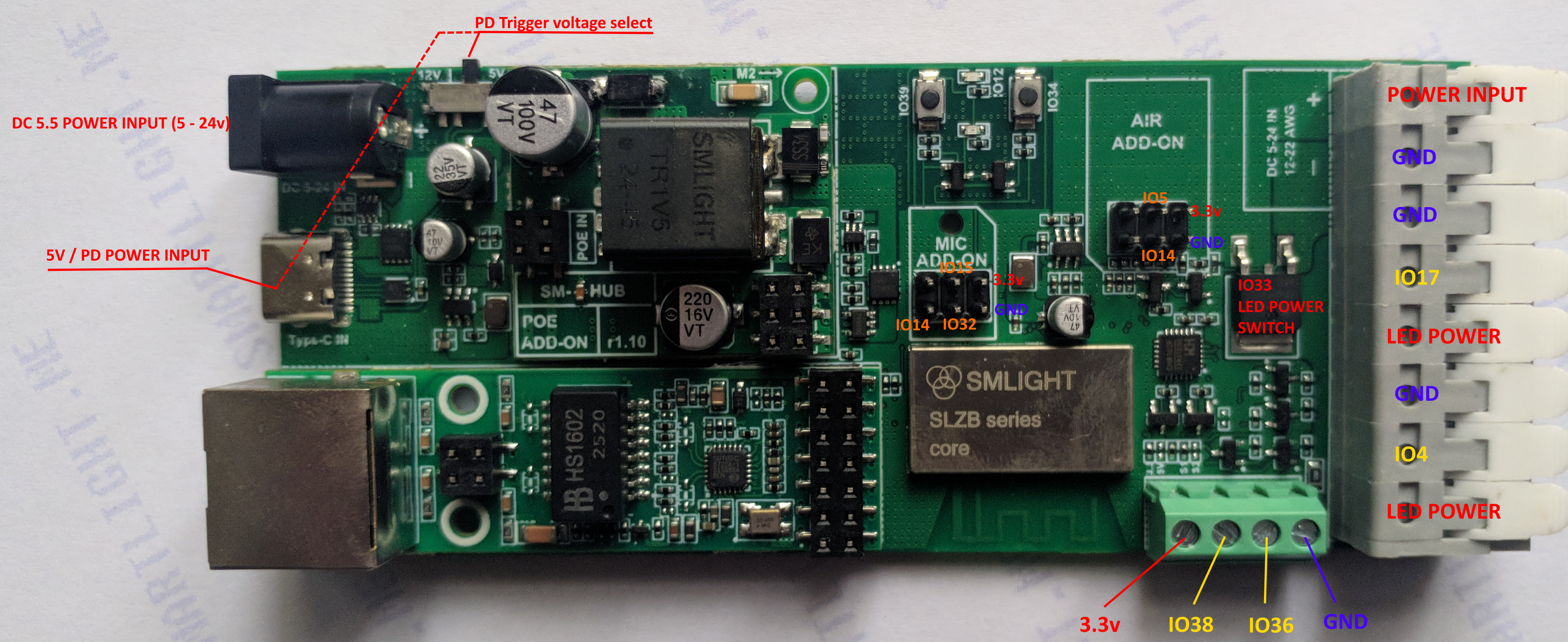
GPIO Allocation
The table below lists all ESP32 GPIOs used by the SLWF-09, their assigned functions, and the type of interface or peripheral they control.
Pins marked with “*” are only used when the corresponding add-on module (Ethernet or Microphone) is installed.
The PoE add-on does not consume any GPIO pins.
| Type | Function | GPIO |
|---|---|---|
| Boot/Prog | Not exposed | GPIO0 |
| LED | On board LED | GPIO2 |
| LED | LED data output 1 (DATA) | GPIO4 |
| LED | LED data output 2 (for clocked LEDs) | GPIO17 |
| I²C | I²C SCL (expansion) (10k pull up) | GPIO5 |
| I²C / Mic | I²C SDA / Mic SCK* (10k pull up) | GPIO14 |
| Mic | Mic WS* | GPIO15 |
| Mic | Mic SD* | GPIO32 |
| Ethernet | PHY RXER* | GPIO13 |
| Ethernet | PHY Clock Enable / OSCEN* | GPIO16 |
| Ethernet | MDIO* | GPIO18 |
| Ethernet | TXD0* | GPIO19 |
| Ethernet | TXEN* | GPIO21 |
| Ethernet | TXD1* | GPIO22 |
| Ethernet | MDC* | GPIO23 |
| Ethernet | RXD0* | GPIO25 |
| Ethernet | RXD1* | GPIO26 |
| Ethernet | CRS_DV* | GPIO27 |
| Relay | LED power line control | GPIO33 |
| Button | Button 1 | GPIO34 |
| DIY1 | DIY input/output | GPIO36 |
| Ethernet | Ethernet detect* | GPIO37 |
| DIY2 | DIY input/output | GPIO38 |
| Button | Button 2 | GPIO39 |
| Reserved | Not connected (NC) | GPIO35 |
Troubleshooting
This section lists common issues you may encounter while using the SLWF-09, along with their possible causes and solutions.
6.1 Power Issues
| Problem | Possible Cause | Solution |
|---|---|---|
| No power LED when connected |
- Incorrect power supply voltage - Incorrect WLED relay settings |
- Verify voltage matches LED strip (5V, 12V) - "Relay GPIO" setting should be GPIO33 |
| Device powers on but LEDs do not light |
- Incorrect LED wiring - LED relay is not configured |
- Verify data and ground connections - Configure LED relay in WLED to GPIO33 |
6.2 Network Connection Problems
| Problem | Possible Cause | Solution |
|---|---|---|
| Cannot find WLED Wi-Fi AP on first boot | - Device already connected to a previous network | - Reset Wi-Fi settings by holding BOOT button for 5+ seconds until LED blinks rapidly |
| Cannot connect to home Wi-Fi | - Wrong SSID/password - Unsupported 5 GHz Wi-Fi |
- Double-check credentials - Ensure router has 2.4 GHz enabled |
| Ethernet not working (with add-on) | - Module not fully inserted - No DHCP from router |
- Reseat Ethernet module - Try a different cable/port - Check if IP is assigned in router |
6.3 LED Output Issues
| Problem | Possible Cause | Solution |
|---|---|---|
| LEDs flicker or show wrong colors | - Voltage drop on long runs - Poor grounding - Incorrect LED voltage |
- Use power injection - Ensure common ground - Match LED strip voltage to power supply |
| Only first few LEDs light up | - Power not sufficient - WLED LED count too low |
- Increase power supply capacity - Set correct LED count in WLED |
6.4 Add-on Module Problems
| Problem | Possible Cause | Solution |
|---|---|---|
| PoE not powering device | - Non-PoE switch/injector - Incorrect PoE standard |
- Use IEEE 802.3af compliant PoE source |
| Microphone not detected | - Module not inserted fully - Sound reactive mode not enabled in WLED |
- Reinsert module correctly - Enable "Sound Reactive" in WLED settings |
6.5 Firmware & Reset
| Problem | Possible Cause | Solution |
|---|---|---|
| WLED interface not loading | - Firmware corrupted - IP conflict |
- Reflash firmware via Web Flasher |
| Device unresponsive after update | - Incorrect firmware build | - Flash with correct SLWF-09 firmware using USB-C and web flasher |
6.6 Support
If problems persist:
-
Visit the documentation at https://smlight.tech/support/manuals/public/books/slwf-09
-
Use the Web Flasher to reinstall firmware.
-
Contact SMLIGHT Support with your purchase details and a description of the issue.
Technical Specifications
The following table lists the key hardware and electrical specifications of the SMLIGHT SLWF-09 LED controller and its supported add-on modules.
7.1 Main Board
| Parameter | Specification |
|---|---|
| MCU | ESP32-D0WD-V3, dual-core 240 MHz |
| Flash Memory | 16 MB |
| Default Firmware | WLED (latest stable release) |
| Power Input Options | USB-C (5V or 12V), DC plug-in terminal (5V–12V DC), VIN fast-clips terminal (5V–12V DC), PoE via add-on (5V output) |
| LED Output Channels | 2 channels (expandable up to 4 via DIY GPIO) |
| Supported LED Types | WS2812B, SK6812, APA102, and other 3-wire or 4-wire addressable LEDs |
| Max LED Voltage | 12V |
| Max LED Current |
With an external PSU (current passes through the controller terminals) - up to 20A. Using DC5.5 - up to 3A. Using POE Addon - up to 800mA. |
| Data Level Shifting | On-board 3.3V → 5V |
| Connectivity | Wi-Fi 2.4 GHz (IEEE 802.11 b/g/n), Ethernet via add-on |
| USB Interface | USB-C with UART auto-programming |
| Buttons | 2 buttons, fully configurable |
| Operating Temperature | -10 °C to +60 °C |
| Dimensions | 57 × 30 × 23 mm |
7.2 Ethernet Add-on (Optional)
| Parameter | Specification |
|---|---|
| Ethernet PHY | LAN8720 |
| Speed | 10/100 Mbps full-duplex |
| Connector | RJ45 with integrated magnetics and status LEDs |
| Power Requirement | Powered by main board |
| Dimensions | 60 × 18 × 15 mm |
7.3 PoE Add-on (Optional)
| Parameter | Specification |
|---|---|
| PoE Standard | IEEE 802.3af Class 0 |
| Input Voltage | 37–48 V DC via Ethernet cable |
| Output Voltage | 5 V DC regulated |
| Max Output Power | Recommended long-term power: 4W Maximum peak power: up to 12.95 W |
| Dimensions | 31.5 × 28.7 × 16 mm |
7.4 Microphone Add-on (Optional)
| Parameter | Specification |
|---|---|
| Microphone Type | ICS-43432 digital MEMS |
| Interface | I²S |
| Frequency Response | 60 Hz – 15 kHz |
| Power Requirement | 3.3 V (supplied from main board) |
| Dimensions | 15 × 12 mm |
Frequently Asked Questions (FAQ)
The Ethernet connection is not working, what should I check?
A:
-
Ensure the Ethernet module is fully seated in its connector.
-
Verify the cable and router/switch port are working.
-
Check that your router’s DHCP is enabled.
Does the PoE module support passive PoE?
A: No, only IEEE 802.3af active PoE is supported.
How do I enable sound-reactive effects?
A: Install the Microphone add-on, then enable “Sound Reactive” mode in WLED settings.
Can I use SLWF-09 with ESPHome?
A: Yes, you can flash ESPHome firmware using the web flasher or USB-C. Make sure to configure GPIO mapping according to the “GPIO Allocation” chapter.
Can I run the SLWF-09 in both Wi-Fi and Ethernet modes at the same time?
A: Yes, the ESP32 can maintain Wi-Fi and Ethernet simultaneously. However, WLED will usually prioritize Ethernet for control traffic.
How do I reset the device to factory defaults?
A: Reflash device using this tool https://smlight.tech/flasher/#SLWF-09
Can I power the controller by POE and use other power input for the LEDs?
A: You can only use one power source at a time: either PoE or external DC power.
It is STRICTLY FORBIDDEN to power the device simultaneously from different power sources.
Is it normal that powering the unit to I don't see any status led visible?
A: Yes it is normal, by default the indicators are not on but you can press one of the buttons and you will see the LED indication.
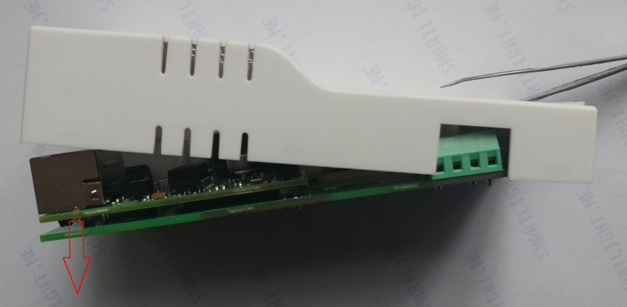
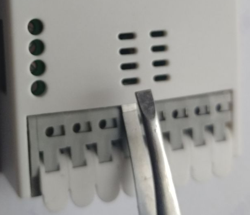
Note about device disassembling
Use a thin and sharp tool for opening the device cover. Insert it into the center of the terminal connector as shown in the photo below:
Once the tool is inserted, start pulling the PCB down from the Type-C connector side: