This feature is supported only by "**U**" series devices and SLZB-Ultima (CPU model: ESP32S3)
USB to Ethernet passthrough mode allows connecting a USB device to your coordinator USB port (directly or via a USB hub) and using such USB devices remotely over IP. For example, a USB Z-Wave adapter can be connected and used remotely, similarly to an Ethernet-based Z-Wave coordinator. ## What devices can be connected? 1. Devices on **CP210x** chipset 2. Devices on **PL2303** chipset 3. Devices on **CH340** chipset 4. Devices on **CH341** chipset 5. Devices on **CH9102** chipset 6. Other **CDC-ACM** devices**CDC-ACM** is typically used in microcontrollers such as the ESP32-S3/S31/P4, STM32, and others. Therefore, if your USB dongle is based on a microcontroller that supports USB, there is a high probability that it uses CDC-ACM.
We cannot guarantee support for all third-party CDC-ACM devices.
## How many USB devices can be connected? ### SLZB-OS versions up to v3.4.2.dev1 **Only one USB device.** ### v3.4.2.dev1 and later Update v3.4.2.dev1 allows the simultaneous use of two USB dongles, provided they are not based on the CH34x chip. Please check the table below for more details:| Device1 Device2** | CP210x | FTDI | CDC-ACM | CH34x |
|---|---|---|---|---|
| **CP210x** | ✅ | ✅ | ✅ | ❌ |
| **FTDI** | ✅ | ✅ | ✅ | ❌ |
| **CDC-ACM** | ✅ | ✅ | ✅ | ❌ |
| **CH34x** | ❌ | ❌ | ❌ | ❌ |
If you are using a **powered** USB hub, please make sure that PoE is disabled! It is **forbidden** to use **PoE** and a **powered** USB hub at the **same** time!
## USB to Ethernet passthrough setup ### 1. Mode select Open the "USB" page and activate "Enable USB to Ethernet passthrough mode" and "Use new USB driver" [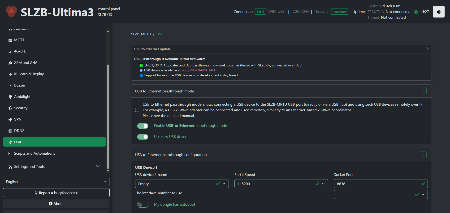](https://smlight.tech/support/manuals/uploads/images/gallery/2026-02/2Bwimage.png)We recommend using the "Use new USB driver" option as the new driver provides greater stability and a wider list of supported USB devices. **The old driver will be removed in future updates!**
**Starting with v3.4.2.dev1 new driver is used by default. There no more driver selector!**
### 2. Connect your USB device and reboot your coordinator ### 3. Select your USB device Select your USB device from the list. [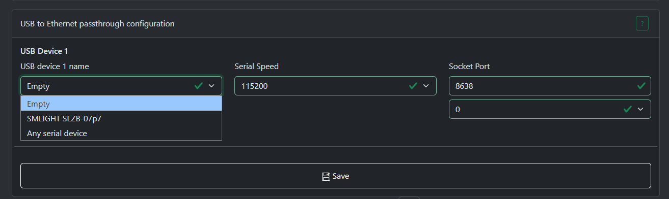](https://smlight.tech/support/manuals/uploads/images/gallery/2026-02/TbNimage.png) "Empty" - passthrough server disabled. "Any serial device" - the system will select the first device found and try to open interface 0.**The interface has been redesigned starting from v3.4.2.dev1**
[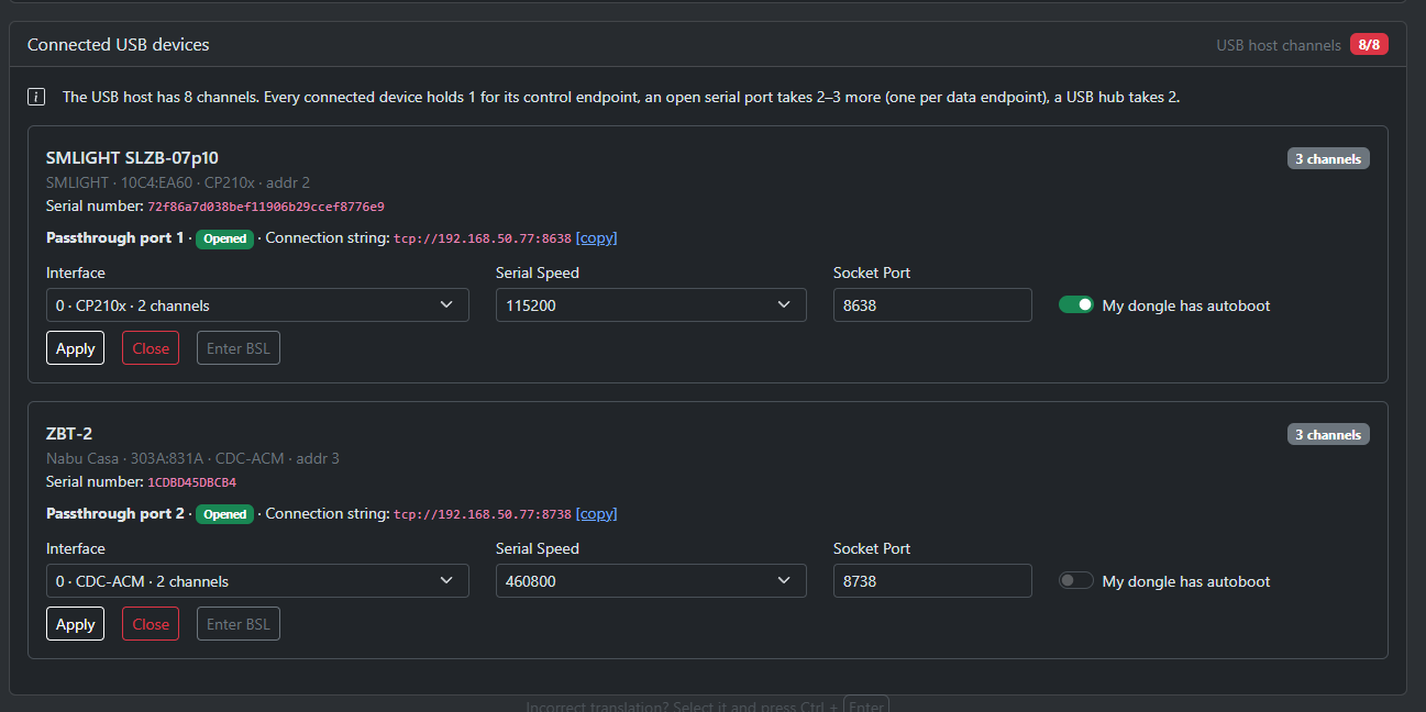](https://smlight.tech/support/manuals/uploads/images/gallery/2026-09/rUIimage.png) Now you need to click the "Open" button on the card for the desired device to enable USB pass-through for it. [](https://smlight.tech/support/manuals/uploads/images/gallery/2026-09/Ovyimage.png) ### 4. Set the serial speed The most common setting is 115200.The serial speed depends on the firmware of your dongle. If you don't know what to choose, please contact the support service of the dongle manufacturer.
### 5. Choose an interface [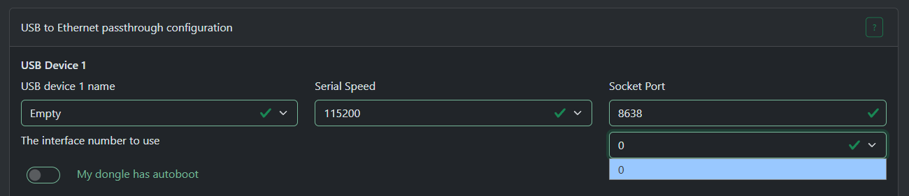](https://smlight.tech/support/manuals/uploads/images/gallery/2026-02/ztgimage.png) Most USB devices will only have one interface - interface 0. But some devices may have several: for example one for `firmware update/debug` and another for `communication`.If your device has multiple interfaces then you will have to try them all until you find correct one.
For **ZWA-2** you need to select interface **1**
**The interface has been redesigned starting from v3.4.2.dev1**
[](https://smlight.tech/support/manuals/uploads/images/gallery/2026-09/YWSimage.png) Key changes in **v3.4.2.dev1** - The interface selector now displays only those supported by the driver. You will no longer see interfaces that the driver cannot open. - The new BSL button uses the DTR/RTS lines to activate your dongle's bootloader (if supported by the dongle). - You can open and close devices, as well as change the baud rate and other settings, in real time. A restart is no longer required. - The list of connected USB devices updates in real time. ### 6. About autoboot Some dongles have an autoboot circuit that puts the radio module into bootloader mode using the DTR/RTS lines, for example SLZB-07p7/p10. For such a dongle to work you need to select the option "My dongle has autoboot".Most dongles that have autoboot use the **CH340** or **CP2102x** chipsets. If you don't know if your dongle has autoboot, please contact the support service of the dongle manufacturer.
### 7. After setup After you have selected all the settings, please click the "Save" button and restart the coordinator for the changes to take effect. ### 8. Host application settings Most programs use the format `tcp://ip:port` or `socket://ip:port`, less often just `ip:port` ``` Examples: tcp://192.168.50.196:8638 socket://192.168.50.196:8638 192.168.50.196:8638 ``` If your host program has "RTS/CTS" or "Hardware flow control" settings, you should select "**disabled**"