
Wiring and Installation
This section explains how to connect the SLWF-09 controller, add-on modules, and LED strips safely and correctly.
Follow all instructions carefully to ensure reliable operation and to avoid damage to the controller or connected equipment.
3.1 Safety Precautions
-
Disconnect power before attaching or removing any cables or add-on modules.
-
Verify that your LED strip voltage matches the power supply voltage (5V, 12V).
-
Never connect different voltage levels (e.g., 12 V LED strip with 5 V power supply).
-
When using PoE, ensure your network switch or injector supports IEEE 802.3af. Please limit the current for the LED strip to 800mA
-
Observe correct polarity when wiring power and LED connections.
3.2 Powering the SLWF-09
You can power the SLWF-09 in three different ways:
-
USB-C port – 5V or 12V
-
Ideal for testing, firmware updates, or low-power LED setups.
-
Supports USB PD for negotiation, can supply 5V or 12V.
-
-
DC plug-in – 5V to 12V DC
-
Connect a DC plug into DC plug-in connector.
-
DC "+" goes to LED strips through the onboard MOSFET (relay) switch or to VCC directly bypassing MOSFET (relay).
-
-
Wire fast-connect terminal – 5V to 12V DC
-
Connect a wire directly to the VIN (+) and GND (–) terminals.
-
VIN also powers the LED strips through the onboard MOSFET switch.
-
-
PoE Module (optional) – IEEE 802.3af
-
Provides 5V 800mA from an Ethernet connection via a PoE-enabled switch or injector.
-
Can be used together with the Ethernet add-on for single-cable operation.
-
3.3 Connecting LED Strips
The SLWF-09 supports most addressable LED protocols, including WS2812B, SK6812, APA102, and others.
Steps:
-
Identify your LED strip’s Data (and optional Clock) lines, V+, and GND.
-
Connect LED OUT 1 or LED OUT 2 on the SLWF-09 to the corresponding LED strip input:
-
Data → DATA pin
-
Clock → CLOCK pin (only for clocked LED types such as APA102)
-
V+ → LED supply voltage (must match power source)
-
GND → Common ground between SLWF-09 and LED strip
-
-
If controlling long LED runs, use an external power injection every several tens of meters to avoid voltage drop.
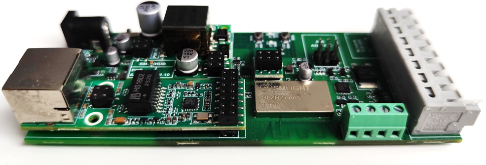
3.4 Installing Add-on Modules
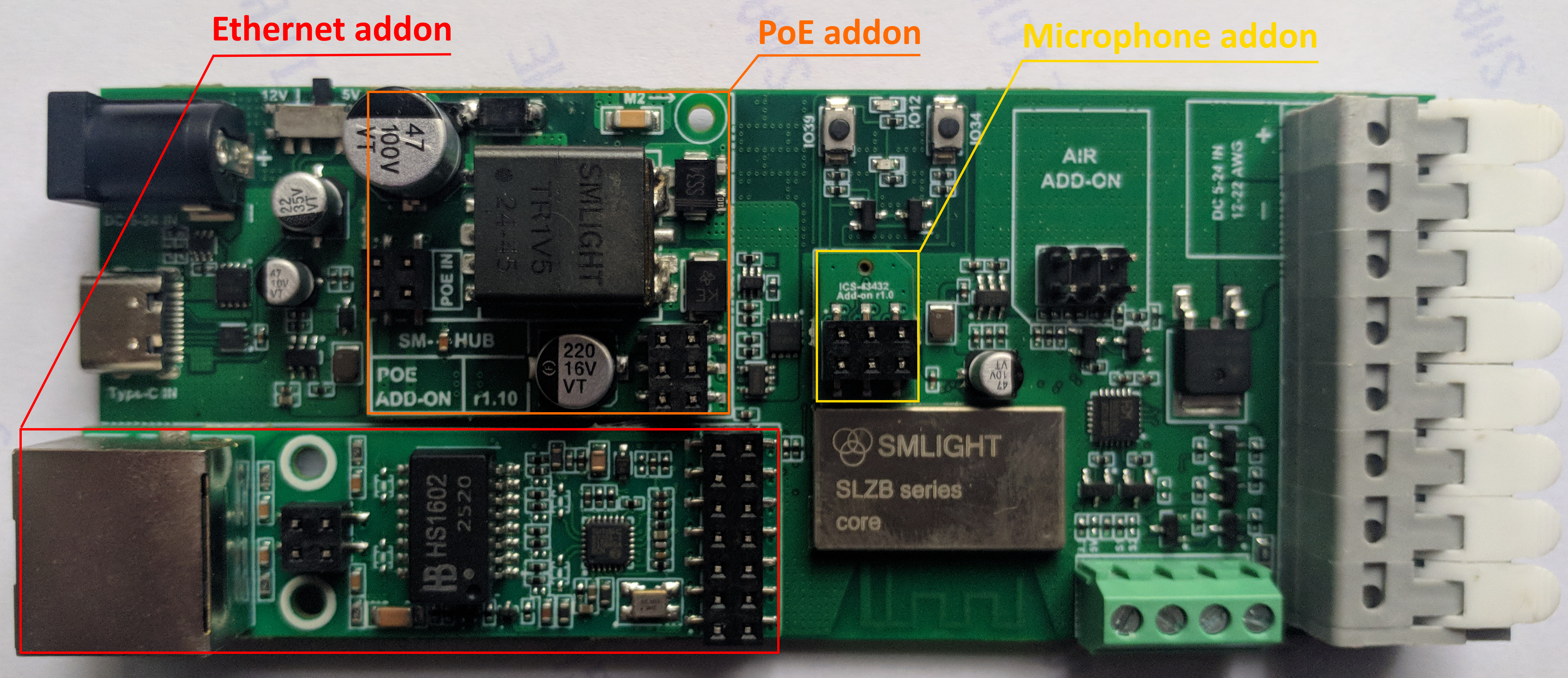
3.4.1 Ethernet Module
-
Align the module with the Ethernet header on the main board.
-
Insert firmly, ensuring the keyed connector matches the socket.
-
Connect your network cable to the RJ45 port.
3.4.2 PoE Module
-
Install the PoE module between the Ethernet add-on and network cable.
-
Connect the network cable from a PoE switch/injector to the module.
-
The module will automatically power the SLWF-09.
3.4.3 Microphone Module
-
Align the module with the MIC header on the main board.
-
Insert carefully; the keyed connector ensures correct orientation.
-
Enable sound-reactive mode in WLED settings.
3.5 First Power-On
-
Double-check all wiring connections.
-
Apply power via your chosen method.
-
Observe the status LEDs:
-
Power LED – solid on when powered
-
Status LED – WLED activity indicator
-
-
Connect to the SLWF-09 via Wi-Fi or Ethernet to complete setup.
3.6 Recommended Installation Tips
-
Mount the SLWF-09 in a ventilated place to protect from dust and accidental contact.
-
For permanent installations, secure cables with strain relief.
-
Keep data wires short to reduce signal degradation.
-
Use twisted pair or shielded cable for long data runs.